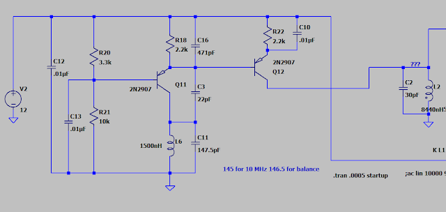
Autocontrol II Reference Oscillator
The autocontrol II units I acquired have been reverse engineered and they are a better design that the originals. I have converted the front oscillator section to silicon transistors (the ubiquitous 2N2222) and it works surprising well with little modification.
This a common base Colpitts oscillator with a center reference at 10 MHz. C11 and L6 form a tank circuit. L6 is the inductor in the attitude indicator, and C11 is the sum of capacitors in parallel (trim, heading indicator, and roll).
C16 is large in relation to C3. This puts the bulk of the feedback into the emitter of Q11. The base of Q11 is biased to about 9 volts which provides plenty of room for the oscillations across the tank circuit. The emitter has its DC current limited by R18 so that peak collector current is about 4 mA - well within what a 2N2222 can handle.
Q11 is well within its limits in silicon. The old germanium transistor was probably hand selected to do this but a modern device is not challenged. The high input capacitance of the transistor is mitigated by the common base design.
Q12 is configured as an emitter follower to prevent the load from affecting the output frequency. The load is the input tank of the discriminator coil.
The oscillator is easier to follow if you remember that the positive and negative pole of the DC power supply are both AC ground. Therefore the feedback is taken between the capacitor network formed by C16 and C3. C3 is small so it doesn't affect the tank circuit too much and it also makes sure the feedback is high. The non-inverting nature of a common base amplifier means the feedback is in phase.
The changes I made to the circuit involve:
- - Using 2N2222 instead of whatever mysterious part numbers were used in germanium
- - Tweaking the bias network to use common values
- - Slightly increasing the emitter resistor to lower current and keep gain under control
- - Increasing C16 to ensure oscillation, modify gain, and use a common part value


Comments
Post a Comment