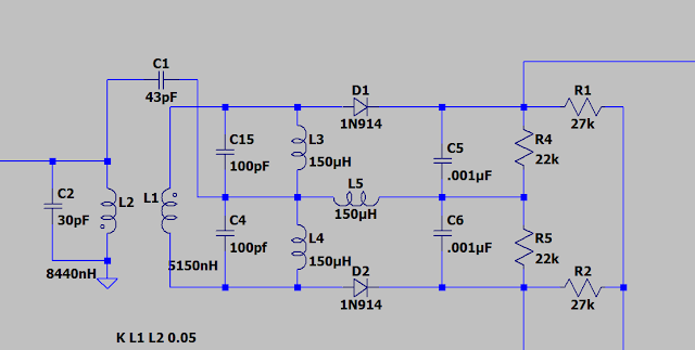
Discriminator Circuit
This is a Foster Seeley FM detector / demodulator circuit. The discriminator coil is the capacitor inductor network at L2 and L1 (up to and including the 100 pF capacitors on the output side.) This is all mounted in a tunable can like an intermediate frequency transformer.
The two inductors are peaked (with ferrous slugs) at 10 MHz. C1 provides capacitive coupling to the voltage divider at C15 and C4 from the top of the primary There are various explanations of how this works but in practice, if the input frequency is above or below the tuned frequency, the amplitude across C15 or C4 goes up or down.
This is rectified by D1 and D2 which conduct if the voltage at the anode gets higher than the cathode. This charges C5 and C6 and provides a differential DC voltage at R4 and R5. R1 and R2 drain DC voltage to ground in a clever manner to be discussed later.
So, this provides a varying DC voltage across the output (R4 and R5) that represent whether the circuit is above or below the center frequency.
This sort of system was very common in the early years of FM radio and television. Most of the circuits you will see use a center tapped coil at the output stage. I have now disassembled three of these and all of them looked handmade to me.


Comments
Post a Comment