Photocell H-Bridge
I've been reverse engineering the Autocontrol II and I will post a bit on its DC amplifier soon, but something I saw got me to re-visit an older project.
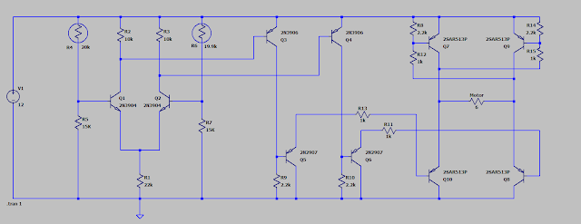
The second section is a sort of DC amplifier. Q3 and Q4 bias themselves as a form of current source (their base drains into the collectors of Q1 and Q2). Therefore they are always on and saturated through resistors R9 and R10. However, if the differential gain is high enough to cut off either Q1 or Q2 their respective collector will be pulled too high by R2 or R3, and Q3 or Q4 will turn off. This will then allw the base of Q5 or Q6 to drain down, which will then turn on either side of the H-bridge formed by Q7 through Q10.
The third portion is the H-bridge which is quite conventional. I've shown those as a rather obscure transistor 2SAR513P but this will actually be a TIP125 as it has an internal fly back diode and so forth. Sadly, this type of Darlington is not a default option in LT Spice and I am too lazy to model it.
The main point is that only one side of the bridge can possibly turn on. Q3 and Q4 are always holding Q5 and Q6 off at all times via the current source draining from the base of Q3/Q4 into the differential amplifier collectors.. Only if one of the collectors of Q1 or Q2 get high enough to shut off the base of Q3 or Q4 can one side or the other of the H-bridge operate. No shoot-through possible.


Comments
Post a Comment